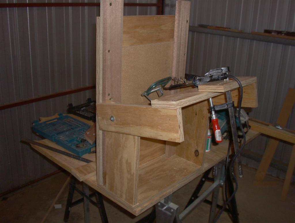
This is an overall view of the cutter from the left hand side. This is a trial fit of all the bits and pieces.
This view shows the cutter positioned ready for work. All that's needed is the can for the melted pitch and the lap itself.
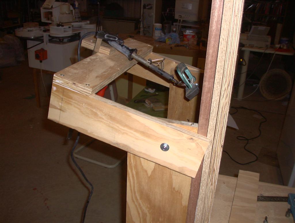
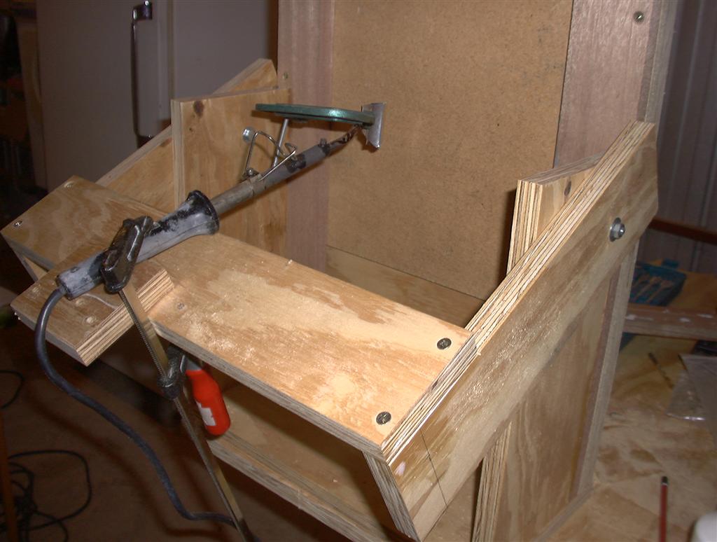
This is an overall view of the cutter from the right hand side. This is a trial fit of all the bits and pieces. As can be seen, the angle of the arms is adjustable to allow the depth of the cut to be varied to suit.
Another view from the near front.in particular, note the high tech soldering iron positioning device!
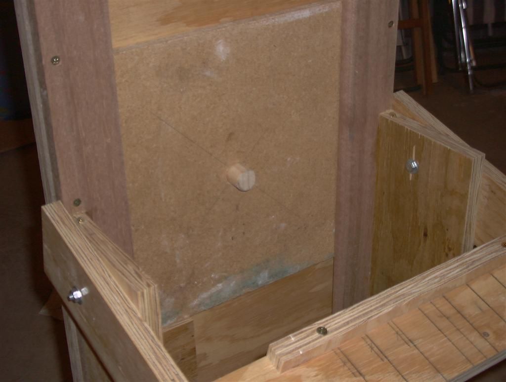
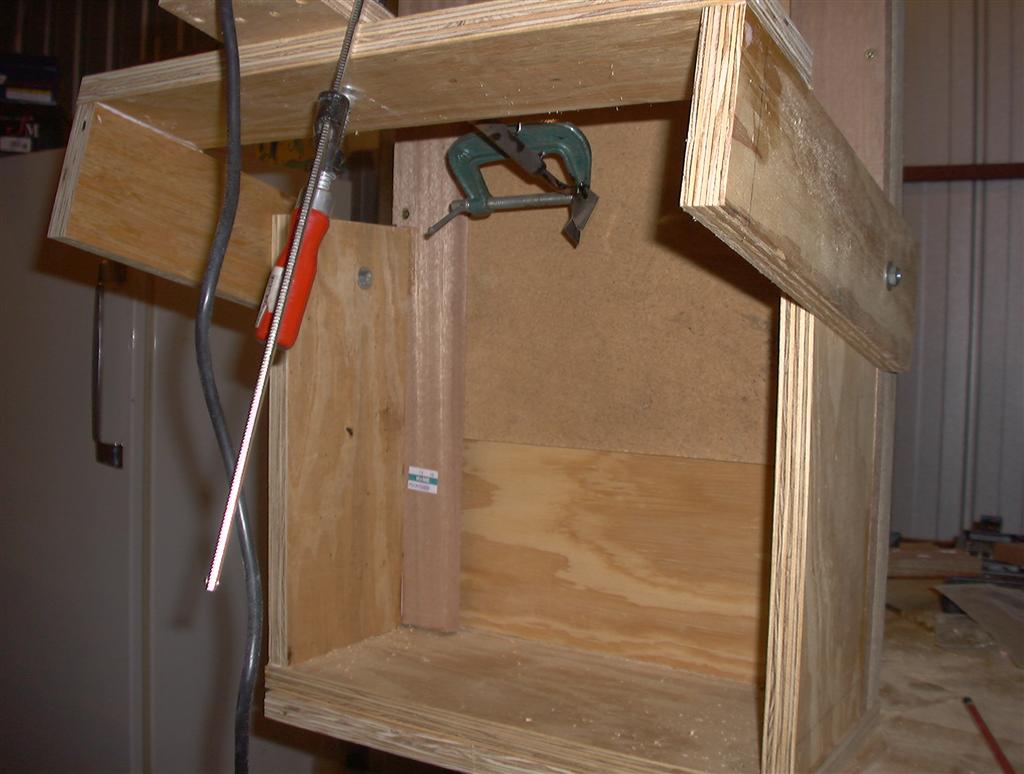
This shows the pivot point to good advantage. The 1 inch block fits into the 1 inch hole drilled in the back of the lap. When all the channels in one direction are cut, I spin the lap 90 degrees and start again.
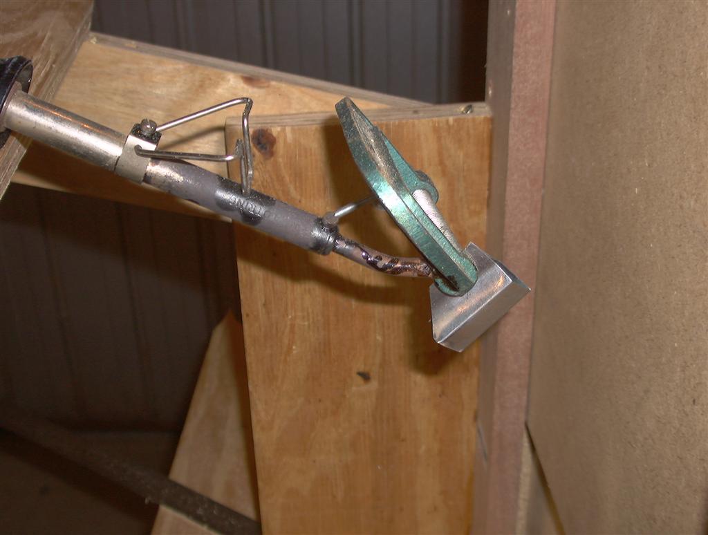
A closeup view from the right side of the shim attached to the soldering Iron.
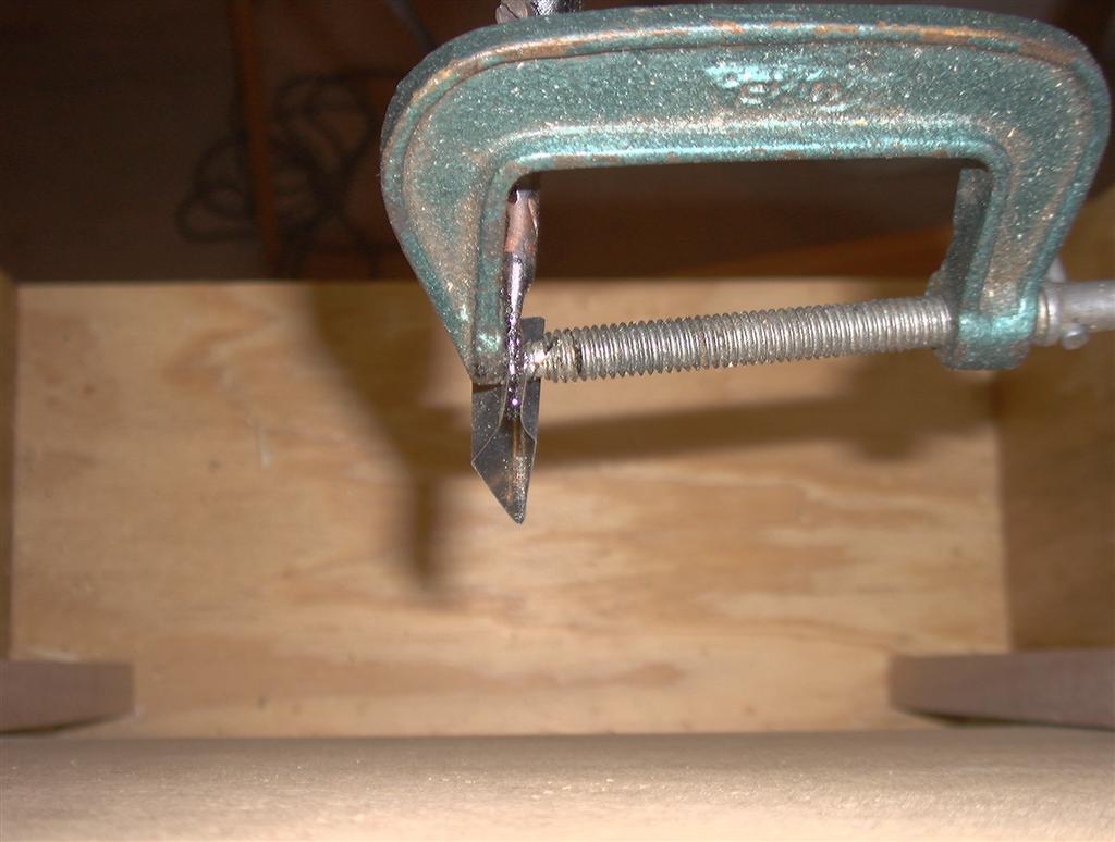
An overhead view of the shim showing the shape that will channelled into the lap.
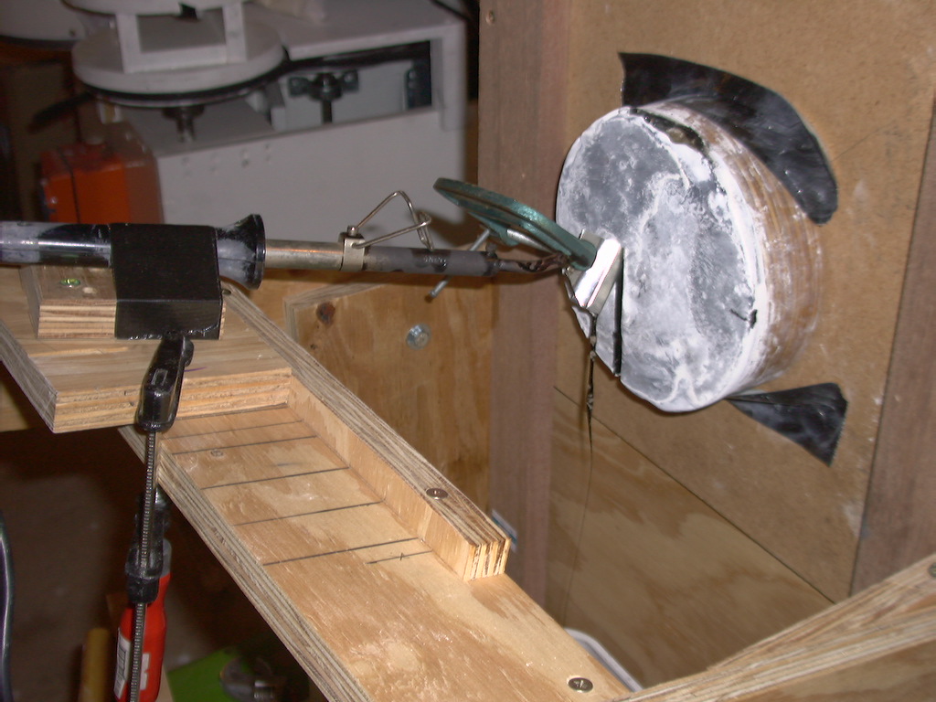
This is the first channel being made. Near the bottom of the cut you can see that the width of the channel changes. I realised after starting the channel that it was slightly too deep and needed to be made slightly shallower.
After the first row of channels were cut, I rotated the lap 90 degrees and prepared to start again. The edge of the lap has not been bevelled yet.
This is the completed lap after finishing the channelling. At this stage the edge bevelling hasn't been done.
Tah dah!!! The completed lap, very nice looking I reckon.
